|
CMU Graphics Lab Motion Capture Database Home | Search | Tools | Info | FAQs | Rendered Movies | Resources |
|
|
|
Carnegie Mellon Graphics Lab: Motion Capture and File Formats
Overview
This document gives an overview of the mocap process at CMU. It is aimed at a student who wants to understand, broadly, how motion is captured, and who wants to do a project (using Maya or C++) with the data.The Things
- The Motion Capture Lab is in the basement of Wean Hall, room 13??.
- The Motion Capture Database is at http://mocap.cs.cmu.edu . The database contains free motions which you can download and use. There is a zip file of all asf/amc's on the FAQs page.
Down in the Mocap Lab
The mocap lab in the basement of Wean contains 12 Vicon infrared MX-40 cameras, each of which is capable of recording 120 Hz with images of 4 megapixel resolution. The cameras are placed around a rectangular area, of approximately 3m x 8m, in the center of the room. Only motions that take place in this rectangle can be captured. If motion of human hands is being captured, more detail is required and the cameras are moved closer to capture a smaller space with higher resolution.
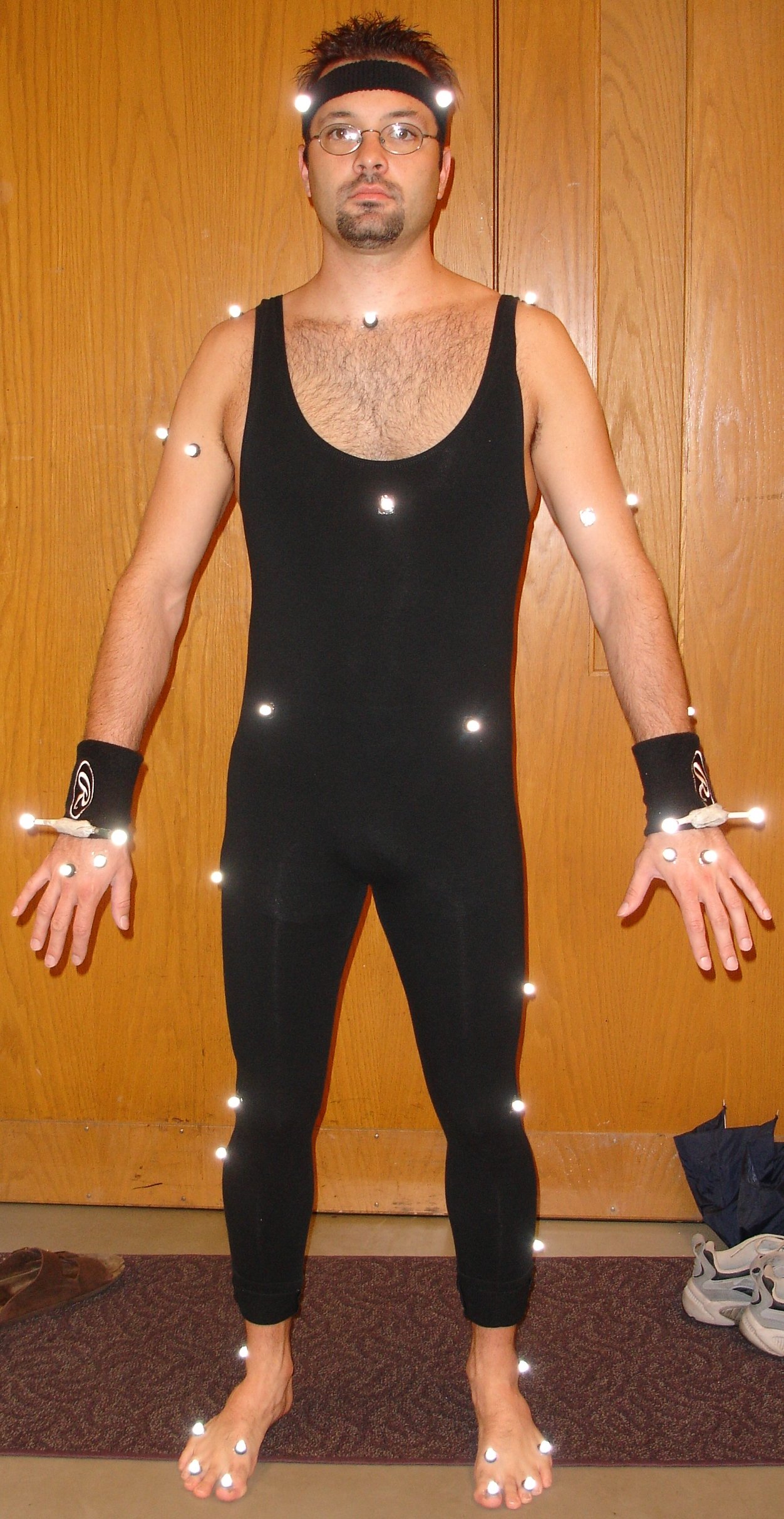
To capture something, small grey markers are placed on it. Humans wear a black jumpsuit and have 41 markers taped on. The Vicon cameras see the markers in infra-red. The images that the various cameras pick up are triangulated to get 3D data.
This 3D data can be used in two ways by you:
- Marker positions You can be handed a file of 3D marker positions, a .c3d . This file is relatively clean - i.e., Marker ``A'' should be labeled Marker ``A'' throughout the motion. But it is your responsibility to figure out what ``A'' means and how it relates to the other markers.
- Skeleton movement Data will be handed to you as either a .vsk/.v pair or .asf/.amc pair (more on that later). The former element of the pair describes the skeleton and its joints: their connections, lengths, degrees of freedom (free, ball and socket, 2 hinges, hinge, rigid), and mathematical transformations. The latter element of the pair contains the movement data. Notes: If a subject/object was captured in multiple clips, you will be handed several .v's or .amc's. Also, something like a hamburger turner, if that's what you're capturing, can have a "skeleton" - even if it's one bone long.
The Vicon software system called "ViconIQ" processes the camera data and ultimately outputs a .vsk/.v. The steps in this process are described in the three subsections following.
The Vicon Skeleton Template
Vicon must be told what skeleton to use, in the form of a .vst, a Vicon Skeleton Template. These can be created in ViconIQ itself, under the modeling tab. The Vicon software comes with documentation on editing them. Visualized, they look like maya skeletons covered in porcupine needles. They specify the skeleton hierarchy, and what markers will be captured to help construct this skeleton. They give approximate bone lengths - the actual length, of course, will depend on the subject/object being captured.
The markers are carefully placed to get maximal information - consider that if you had a hinge joint, 2? 3? markers would define it absolutely. Constraints between markers and joints are also specified, e.g. "the elbow belongs at the y-location of this marker", or "the wrist joint is halfway between these two markers". You get the idea. Constructing .vst's for complex objects requires careful thought and testing.
In the lab, we have pre-tested .vst's for humans and hands. Creating .vst's for simple props is easy.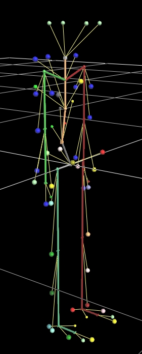 |
 |
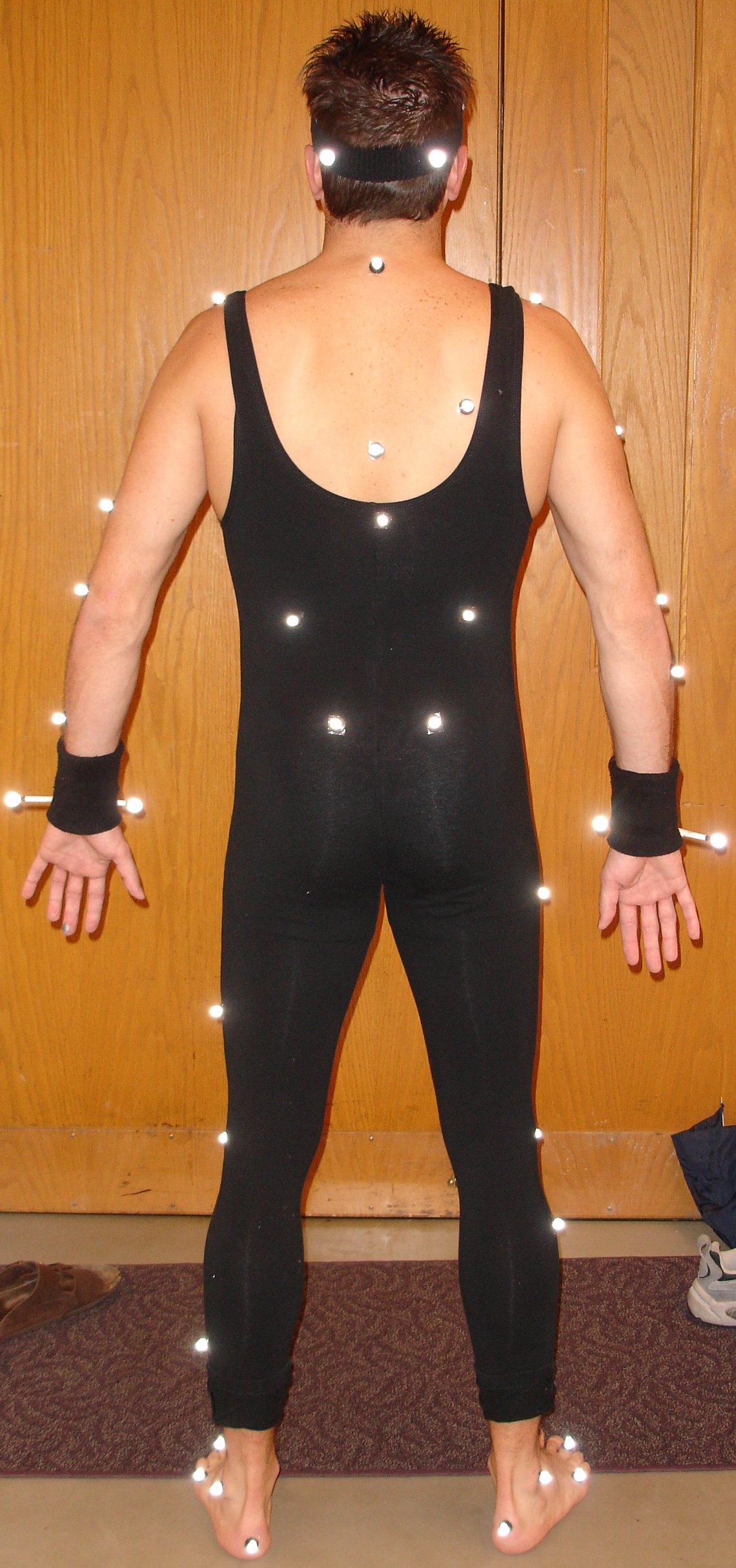 |
| Visualization of the .vst. The balls represent markers; the thick colored segments represent bones. | The marker set. | Back view. |
The Labeling
ViconIQ requires user interaction to start off the skeleton fitting. To process a capture, a segment of motion is loaded onscreen as a point cloud of markers. The user goes through and specifies the correspondence between these markers and the markers in the .vst, e.g. "this white dot is the clavicle marker". From this data ViconIQ can fit a skeleton and determine the skeleton's limb lengths. From here on out the labeling process is automatic. ViconIQ can load up each motion clip and automatically perform a "Kinematic Fit" of the skeleton to the markers. During this time the software uses its knowledge of the skeleton to correct captured marker aberrations. The user can also fix things up by editing the joint rotation/translation graphs directly.The Exporting
While this work is going on each motion clip is stored in a .trial file. When the data is clean, it is time to export useful files. A .vsk of the skeleton is exported. Keep in mind that this .vsk is unique to each person, because each person has different limb lengths. Multiple .v's are exported, one for each motion clip the person performed. Using BodyBuilder, these can be turned into asf/amc's.Documentation on File Formats
The File Formats - c3d
C3d files are binary; check out The Website.The File Formats - asf/amc
The asf/amc format is ascii and is reasonable to parse. Angles are in euler angles. It is documented here.- What are the lengths in CMU's asf/amc files? ASF files in CMU mocap database have ":units->length" set to 0.45. That is because all the values are multiplied by 0.45 before they are stored to file (I am not sure why). Also ASF files are stored in inches, so to convert to meters you need to multiply all length values by the following scale=(1.0/0.45)*2.54/100.0.
The File Formats - vsk/v
The .v file format is binary and is, surprisingly, also reasonable to parse. Angles are in axis-angle format (strange how you can parse them as euler angles and it still looks ok. Bang head here). This document describes how to parse the file. Here are some questions that came up about the format, and some possibly-correct answers (code referred to is James McCann's "C++ code" in the tools page).- In The .V file every bone has 6 values: T-X, T-Y, T-Z, A-X, A-Y, A-Z. Why does every bone has translational dofs? Do you know what these values represent? Are they in local coordinate system or in global coordinate system?
Bone data in the .V file are local or global, depending on the file - it's in the header and depends on the options you choose when doing the File->Export in the vicon software. The code only reads global .V's.
In the .vsk, offsets in constructing the skeleton are naturally local (ie. "move down this amount to get to the knee"). - Does the world translation specify the position of the inboard joint? My suspicion is that the translational dofs in the V-file give the location, in world space, of the inboard joint.
- Why does every bone has 6 values stored independently on how many dofs it has? Is it just what vicon does? Vicon just stores all 6 values. Some bones have translation, some don't. It's just what Vicon does.
- How is rotation represented? What is A-X, A-Y and A-Z? AX AY AZ are axis-angle format. http://en.wikipedia.org/wiki/Axis_angle
- The position data, is it always in millimeters? Don't remember. You should read over the spec for .V files.
- What is the reason for adding the phantom bones in the code?
Phantom bones are there mostly to frighten the undergrads.
Additionally: In ASF: Store a bone start position, and its extent X.
In VSK: Store a bone start position, and its offset from its parent.
So we have an "inversion" in the file format.
In asf, this means that all children of boneB are Xdistance away from boneB.
However, in vsk, all children of boneB can be different distances from boneB.
Now, consider where you have boneB with 2 children, boneC and boneD, in a vsk. Each of the two kids can be a different distance away from boneB. How shall we convert to an asf? Well, we can't. What in the world will be the extent of boneB?
Here's a hack. Let's split boneB up into 3 bones, boneB, boneBC, and boneBD. Give boneB length 0. Have boneBC point towards boneC, and have boneBD point towards boneD. Now the "offsets" of boneC & boneD in the vsk map to the "extents" of boneBC and boneBD in the asf.
boneBC & boneBD are the phantoms.
- Not that this comes up in everday conversation a lot, but what is the toe length? Bones at the end of kinematic chains may have arbitrary lengths since this information isn't stored in the vsk.
The File Formats - txt
- After labeling trajectories in ViconIQ, export .trial file as .c3d file
- Open BodyBuilder software and open .c3d file (icon with red arrow in eclipse)
- Click File > Write ASCII, then choose options
- Choose options for exported markers and .txt filename